

LoRawAN methane gas alarm

LoRawAN methane gas alarm
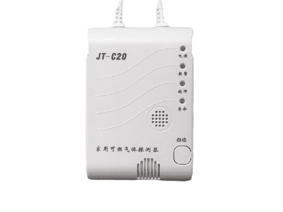
JT-C20.0 Household Combustible Gas Detector (hereinafter referred to as "Detector") is used to detect the content of natural gas (the main component methane CH4) in non-explosion-proof places of civil buildings and prevent gas leakage and explosion accidents. The internal wireless module of the detector can form a star network with the gateway, which is convenient for network maintenance, high reliability and strong scalability. When the detector detects that the natural gas leakage in the environment reaches the alarm setpoint, the detector issues an audible and optical alarm signal and actively reports the alarm data to the LoRaWAN gateway. Special LED indicator indicates working status, alarm status, fault status; The use of the most advanced semiconductor gas sensor, high sensitivity, good selectivity, stable performance, long service life; The detector has strong anti-interference ability and strong ability to adapt to the environment; With self-test function;
Technical index
● Operating voltage AC220V±15%, not more than 1.5W.
● Operating temperature range: -10°C ~ 55°C.
● Operating humidity range: relative humidity is not more than 95% (at 40°C).
● Use pressure range: 86kpa ~ 106kpa (*101kpa is a standard large air pressure).
● Alarm Setpoint: Methane: 8% LEL.
● Warm-up time: 120S.
● Sensor life: 5 years in normal atmospheric environments.
● The detector wireless reception sensitivity <-136dBm, working bandwidth -125kHz, the maximum transmit power meets the power limitation requirements of different regions of LoRaWAN specification.
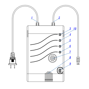
Detector appearance structure and size
● Dimensions: 120mm*80mm*37mm
● Detector structure description: (1) power cord (2) linkage line (3) power indicator (4) alarm indicator (5) fault indicator (6) life indicator (7)Sound hole (8) Inlet hole (9) Self-test button (10) Outlet hole
Functional feature description:
Serial number | Function | Functional description |
1 |
Warm-up status | After installation, power on the detector and the buzzer beeps for power Audible to indicate that the power supply is on. The detector enters the preheating state of the gas-sensitive element, the power supply The green LED flashes and after about 120 seconds the gas-sensitive element warms up and the power supply is green The LED is solid on. |
2 | Monitor the status | After the warm-up state is over, the power supply green LED is solid and the detector enters normal Monitor the status. |
3 | Alarm status | When the detector detects a methane (CH4) leak that reaches the alarm threshold, it is repeated several times After the judgment of the buzzer issued a discontinuous alarm code, the alarm red indicator light is solid on, enter Alarm status. When the gas concentration drops below the alarm threshold, the detector is judged by many times The action resumes to the normal monitoring state. |
4 |
Failure status | When the sensor fails (such as a fault, a broken circuit, etc.), the fault is yellow The alarm indicator light is flashing, indicating that there is a fault, such as the fault can not be eliminated in time Multiple times to judge the buzzer to issue a continuous beep code, the fault yellow indicator light is solid on, enter Enter the fault alarm state. After the fault is lifted, the detector automatically returns to normal monitoring after multiple judgments State. |
5 | Sensor failure status | When the detector detects that the sensor has reached the age of the sensor failure, The life indicator flashes, indicating that the user has failed the sensor and needs to be replaced in time Utensil. |
6 | Self-test status | When the detector's self-test button is pressed, the life indicator flashes and the alarm points red The light is on and the buzzer beeps (at this point, if the self-test button is pressed again, it is reported.) The alarm starts the linkage function, and then the linkage signal is output between the 7S-30S and the relay touches Point switching, hit the valve line to output a low pressure pulse signal), followed by a fault yellow indicator On, the buzzer emits a fault tone, and finally the detector returns to normal monitoring state. Note: In order to ensure the normal operation of the product, during the 120s of the product power preheating Please do not press the self-test key! |
7 | Data reporting | There are two ways to report data: 1. Magnetic departure report data: the magnet trigger is greater than 2s, and the red light is lit 2. Regular active reporting data: the timing reporting period and the timing reporting time can be set, the value range of the timing reporting period is 600~86400S, and the regular reporting time value range is 0~23H. After setting, the reporting time is calculated according to the metered DeviceEui, the timing reporting period, and the timing reporting time. timing The default value of the reporting period is 86400S. |
8 |
Read probe status and status alerts | Support gas detector status reading, read every 10s; The detector status changes immediately on the alarm data: Reporting data (hexadecimal) 24 1922 16839E27ED 1401 1B04 1203 0B00000000 1A0053 330000 2300 C1 24: Frame head 19: Packet number 16: Device (table number) 14: Pulse constant 1B: Device type 12: Mode 1A: Voltage 33: Status Word 23: Trigger Source C1: Cumulative Sum Status words: B15=1: Warm-up B13=1: Sensor end-of-life B11=1: Device status acquisition failed B7 = 1: Alarm status B6 = 1: Failure status |
9 |
Wireless setting parameters | Parameters can be set in two ways: 1. Wireless far-field setting parameters: After the detector completes the information report, it can be realized through the cloud platform. 2. Wireless near-field setting parameters: realized through production setting tools. The Near Field parameter is set to Wireless Communication Mode. |
CONTACT US
Address:9th Floor, Block A, Building 1, International Innovation Valley, Xili Community,Nanshan District,Shenzhen.
|